Great-plains NTA3007HD Predelivery Manual User Manual
Browse online or download User Manual for Gardening equipment Great-plains NTA3007HD Predelivery Manual. Great Plains NTA3007HD Predelivery Manual User Manual
- Page / 70
- Table of contents
- BOOKMARKS
- Manufacturing, Inc 1
- Table of Contents 3
- 166-207M 03/29/2010 4
- Important Safety Information 5
- Use A Safety Chain 6
- Avoid High Pressure Fluids 6
- Tire Safety 6
- Practice Safe Maintenance 7
- Safety At All Times 7
- Introduction 8
- Getting Started 9
- Forklift 9
- Shipment Inventory 10
- Unloading the Racks 11
- 166-207Q 03/29/2010 12
- Bin Rack 13
- 03/29/2010 166-207Q 15
- Cart Rack 18
- Tools Required 33
- Pre-Assembly Checklist 33
- Assembly (General Sequence) 33
- Assembly 34
- Assemble Cart Front Wheels 35
- Assemble Contact Drive Wheels 35
- Adjusting Drive Wheels 35
- Assemble & Install Meters 36
- Meters Face Same Direction 36
- Bin Lids and Silicone Sealant 37
- Bin Lids 37
- Bin Lid Closing 38
- Bin Strainer 38
- Bin Ladder Mounting 39
- Assemble Ladder to Cart Frame 40
- Verify Ladder Function 41
- Assemble Bins to Frame 42
- Bins Mounted 42
- Adjustment) 46
- Assemble Center Towers 47
- Assemble Wing Towers 48
- Wing Tower Placement 48
- Wing Tower Hoses 49
- Seed Hose Port Maps: 49
- Assemble Tongue and Jack 50
- Assemble Pullbars (front) 51
- Assemble Pullbars (back) 51
- Assemble Hitch 52
- Air Drill Hitched to Tractor 52
- Route Hoses 53
- Hydraulic Hose Hookup 54
- Hydraulic Hose Installation 55
- Opener Lift Hydraulics 56
- Wing Fold 56
- Wing Opener Tilt Hydraulics 57
- Wing Tilt 57
- Transport Hook 58
- Wing Movement During Hook 58
- Auger Hydraulics 59
- Auger Latched for Movement 60
- Deploying the Auger 60
- Fan Hydraulics 61
- Fan Mount 61
- Fan/Auger Selector Valve 61
- Weight Transfer Hydraulics 62
- Adjusting Weight Transfer 62
- Electric Harness (Monitor) 63
- Electric (Lights) 63
- Brake Hookup (Option) 64
- Parking Brakes 65
- Air Brakes 66
- Air Brake Connectors 66
- Hydraulic Brakes 67
- International Decals 68
- Salina, Kansas 67402-5060 USA 70
Summary of Contents
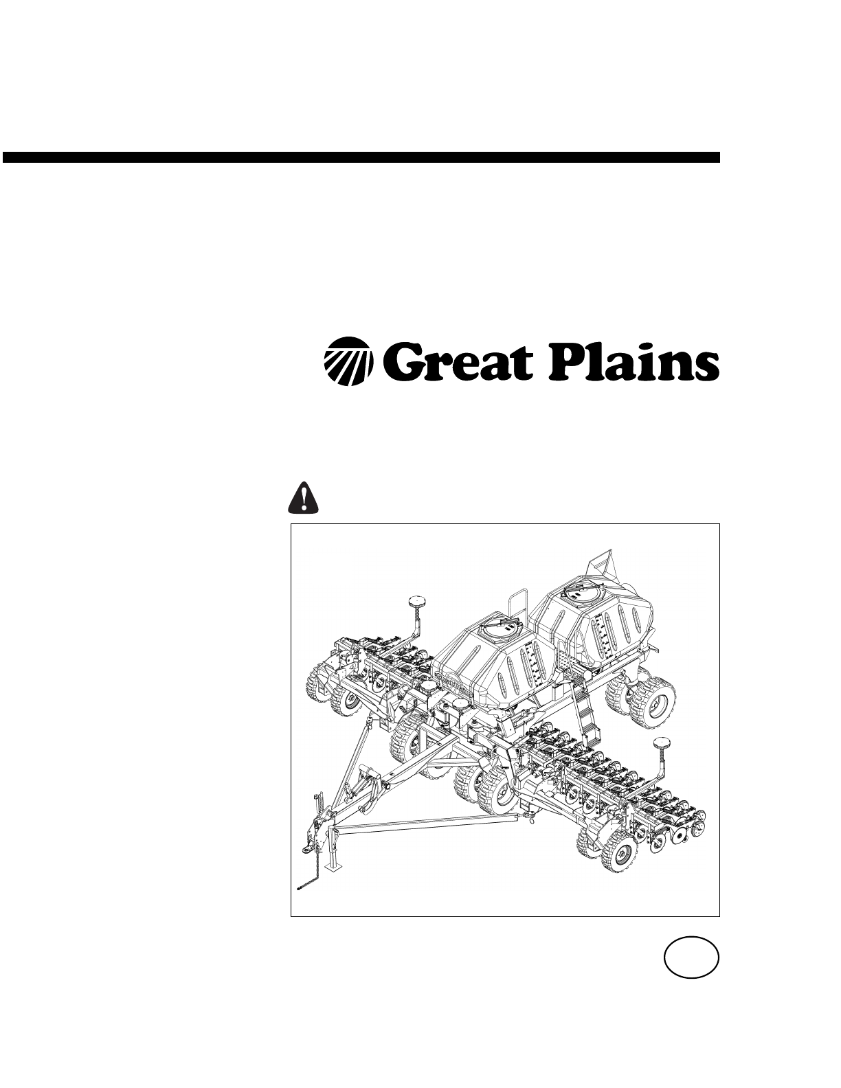
Manufacturing, Inc.www.greatplainsmfg.com© Copyright 2010 Printed 03/29/2010 166-207QExport Pre-Delivery InstructionsNTA907HD9m/30ft No-Till Heavy Dut
6 NTA907HD166-207Q 03/29/2010Shipment InventoryThis drill was disassembled and attached to 3 racks fortransporting. Remove all loose accessories (list
Unloading the Racks 703/29/2010 166-207QUnloading the RacksRefer to Figure 8 and Figure 9Opener RackREMOVE RH and LH OPENER SECTIONS (fromeach side
8 NTA907HD166-207Q 03/29/2010Refer to Figure 10Place 4 straps as shown to lift the opener section.Figure 10Strap Placement for Lifting OpenerSections7
Unloading the Racks 903/29/2010 166-207QRefer to Figure 11Bin Rack1. Remove all loose parts inside the bins.These partswill be necessary in the assemb
10 NTA907HD166-207Q 03/29/2010Refer to Figure 13BIN RACK:• 2 Bins• 2 Wing Weldments• 4 Loose WheelsRefer to Figure 144. Remove one bin resting it on f
Unloading the Racks 1103/29/2010 166-207QRefer to Figure 155. Remove 4 loose wheels stored under the bins (sothere is no likelihood of their getting p
12 NTA907HD166-207Q 03/29/2010Refer to Figure 17Two Wing WeldmentsRefer to Figure 187. Remove one wing weldment at a time by first remov-ing the one bo
Unloading the Racks 1303/29/2010 166-207QRefer to Figure 198. Place an overhead strap attached to the forkliftthrough the top hole in one wing weldmen
14 NTA907HD166-207Q 03/29/2010Refer to Figure 22Cart Rack• 1 Cart Main Frame• 1 Auger• 2 Pullbars• 1 Tongue with Hitch• 1 Cart Fan Assembly• 2 Wing Fr
Unloading the Racks 1503/29/2010 166-207QRefer to Figure 24LOOSE PARTS3. Remove all loose parts that you can access.Refer to Figure 254. Remove 4 bin
16 NTA907HD166-207Q 03/29/2010Refer to Figure 26LOOSE PARTS6. Remove later: 2 Meter boxes wrapped in plastic (onbottom of rack underneath all the othe
Unloading the Racks 1703/29/2010 166-207QRefer to Figure 27THE AUGER (Option)7. With tin snips, remove metal banding securingthe auger in the two cra
18 NTA907HD166-207Q 03/29/2010Refer to Figure 29THE FAN9. Remove cart fan from rack.Refer to Figure 3010. The cart fan is secured to the rack with 4
Unloading the Racks 1903/29/2010 166-207QRefer to Figure 31CART MAIN FRAME11. Remove 6 U-bolts located at each side and endsecuring the cart main fra
20 NTA907HD166-207Q 03/29/2010Refer to Figure 3313. Place 2 straps on back of cart to lift cart out of rack.Refer to Figure 3414. Lifting the cart fra
Unloading the Racks 2103/29/2010 166-207QPULLBARSRefer to Figure 3515. Remove metal banding securing the end of thepullbars to the rear end of the t
22 NTA907HD166-207Q 03/29/2010Refer to Figure 3717. Using 2 straps, place one at each end and removeone pullbar.Refer to Figure 3818. Remove 2nd pull
Unloading the Racks 2303/29/2010 166-207QRefer to Figure 39THE TONGUE19. Place 2 forklift straps at each end of tongue (asshown).Refer to Figure 40(St
24 NTA907HD166-207Q 03/29/2010Refer to Figure 4120. Remove 4 U-Bolts securing the rear end oftongue to the rack.Refer to Figure 4221. Remove one bolt
Unloading the Racks 2503/29/2010 166-207QRefer to Figure 4322. Remove tongue from rack.Refer to Figure 4423. Place 2 straps, one at each end of one wi
iii03/29/2010 166-207M© Copyright 2009, 2010. All rights ReservedGreat Plains Manufacturing, Inc. provides this publication “as is” without warranty o
26 NTA907HD166-207Q 03/29/2010Refer to Figure 45THE 2 WING FRAME UNITS24. Remove 2 bolts securing hoses to one wingframe unit.Refer to Figure 4625. R
Unloading the Racks 2703/29/2010 166-207QRefer to Figure 4727. Remove one bolt securing the other end of thewing frame to rack.Refer to Figure 4828.
28 NTA907HD166-207Q 03/29/2010Refer to Figure 4929. Remove 2 meters (wrapped in plastic).Refer to Figure 5030. Unbolt the 2nd wing frame unit repeatin
Assembly Sequence and Preparation 2903/29/2010 166-207QAssembly Sequence and PreparationInstructions for assembling the implement begin in thenext sec
30 NTA907HD166-207Q 03/29/2010AssemblyNTA907HD Fully AssembledRefer to Figure 51LRUDFBLRFigure 51NTA907HD Assembled29423Figure 52NTA907HD0337
Assembly 3103/29/2010 166-207QAssemble Cart Front Wheels(see Parts Manual page: Cart Transport Wheels withoutBrakes. If machine has optional brake equ
32 NTA907HD166-207Q 03/29/2010Assemble & Install Meters(see Parts Manual section: Meter Box Assembly)(see Operator Manual section: Adjustments)Ref
Assembly 3303/29/2010 166-207QBin Lids and Silicone Sealant(see Parts Manual section: Bin Assembly)(see Operator Manual section: Operating Instruction
34 NTA907HD166-207Q 03/29/2010Bin Lid ClosingRefer to Figure 611. Swing lid over opening until capture hook is cen-tered on U-bolt .2. Open handle a
Assembly 3503/29/2010 166-207QAssemble 2 Ladders Inside Bins(see Parts Manual section: Bin Assembly)Refer to Figure 63MAKE SURE:Make sure to install l
166-207M 03/29/2010
36 NTA907HD166-207Q 03/29/2010Assemble Ladder to Cart Frame(see Parts Manual section: Walkboard and Ladder)(see Operator Manual section: Operating Ins
Assembly 3703/29/2010 166-207QVerify Ladder Function(see Parts Manual section: Walkboard and Ladder)(see Operator Manual section: Operating Instructio
38 NTA907HD166-207Q 03/29/2010Assemble Bins to Frame(see Parts Manual section: Bin to Frame)Refer to Figure 68Bins MountedRefer to Figure 69Figure 68A
Assembly 3903/29/2010 166-207QAssemble Center Opener Weldment(see Parts Manual section: Opener Mount to Frame)Refer to Figure 70 and Figure 71Orientat
40 NTA907HD166-207Q 03/29/2010Assemble Folding Wing Weldments(see Parts Manual section: Wing to Frame)Refer to Figure 72Step 1:• Remove wing fold pin
Assembly 4103/29/2010 166-207QRefer to Figure 74Step 3:1. Coat pivot holes in frame with antisieze com-pound.2. Put shim stack (from Step 2) over piv
42 NTA907HD166-207Q 03/29/2010Assemble Opener Mounts to Wing(see Parts Manual section: Opener Mount to Wing)(see Operator Manual section: Opener Sub-F
Assembly 4303/29/2010 166-207QAssemble Center Towers(see Parts Manual section: Tower Assembly)Refer to Figure 77With drill raised (so openers are drop
44 NTA907HD166-207Q 03/29/2010Assemble Wing Towers(see Parts Manual section: Tramline Mounting)Refer to Figure 78To mount tower:1. Dismount opener spr
Assembly 4503/29/2010 166-207QWing Tower HosesRefer to Figure 80With drill raised (so openers are dropped down), hosesshould be as short as possible.S
Important Safety Information 103/29/2010 166-207QImportant Safety InformationLook for Safety SymbolThe SAFETY ALERT SYMBOL indicates there is apotenti
46 NTA907HD166-207Q 03/29/2010Assemble Tongue and Jack(see Parts Manual section: Tongue to Frame)Refer to Figure 81TongueJackParking(see Operator Manu
Assembly 4703/29/2010 166-207QAssemble Pullbars (front)(see Parts Manual section: Hitch)Refer to Figure 83Assemble Pullbars (back)(see Parts Manual se
48 NTA907HD166-207Q 03/29/2010Assemble Hitch(see Parts Manual page: Hitch)Refer to Figure 85Air Drill Hitched to Tractor(see Operator Manual section:
Assembly 4903/29/2010 166-207QRoute Hoses(see Parts Manual section: Hydraulics)Refer to Figure 87Hydraulic hoses will be routed through the right bulk
50 NTA907HD166-207Q 03/29/2010Hydraulic Hose HookupHigh Pressure Fluid Hazard:Escaping fluid under pressure can have sufficient pressure topenetrate the
Assembly 5103/29/2010 166-207QHydraulic Hose InstallationRefer to Figure 90Hoses are labeled at both ends.Hoses are already hooked up to the valve at
52 NTA907HD166-207Q 03/29/2010Opener Lift Hydraulics(see Parts Manual section: Opener Lift Hydraulics)(see Operator Manual section: Operating Instruct
Assembly 5303/29/2010 166-207QWing Opener Tilt Hydraulics(see Parts Manual section: Wing Opener Tilt Hydrau-lics)(see Operator Manual section: Operati
54 NTA907HD166-207Q 03/29/2010Transport Hook-Wing Fold Hydraulics(see Parts Manual section: Transport Hook and FoldHydraulics)(see Operator Manual sec
Assembly 5503/29/2010 166-207QAuger Hydraulics(see Parts Manual section: Fan and Auger Hydraulics)(see Operator Manual section: Operating Instructions
2 NTA907HD166-207Q 03/29/2010Use A Safety Chain▲ Use a safety chain to help control drawn machinery shouldit separate from tractor draw-bar.▲ Use a ch
56 NTA907HD166-207Q 03/29/2010Auger Latched for Movement(see Operator Manual section: Auger Operations)Latch the auger into its cradles and pin the ar
Assembly 5703/29/2010 166-207QFan Hydraulics(see Parts Manual section: Fan and Auger Hydraulics)(see Operator Manual section: Fan Operation)Refer to F
58 NTA907HD166-207Q 03/29/2010Weight Transfer Hydraulics(see Parts Manual section: Weight Transfer Hydraulics)(see Operator Manual section: Adjusting
Assembly 5903/29/2010 166-207QElectric Harness (Monitor)(see Parts Manual section: Monitor)Refer to Figure 108Locate and install system components as
60 NTA907HD166-207Q 03/29/2010Brake Hookup (Option)Two air drill braking (trailer braking) systems are avail-able:• Dual-line air system with independ
Assembly 6103/29/2010 166-207QParking Brakes(see Parts Manual section: Parking Brakes)(see Operator Manual section: Brake Operation)Refer to Figure 11
62 NTA907HD166-207Q 03/29/2010Air Brakes(see Parts Manual section: Air Brakes)(see Operator Manual section: Brake Operation)Refer to Figure 115Service
Assembly 6303/29/2010 166-207QHydraulic Brakes(see Parts Manual section: Hydraulic Brakes)(see Operator Manual section: Brake Operation)Refer to Figur
64 NTA907HD166-207Q 03/29/2010International Decals(see Parts Manual section: International Decals)Refer to Figure 120Figure 120International Decals294
Important Safety Information 303/29/2010 166-207QPractice Safe Maintenance▲ Understand procedure before doing work. Use propertools and equipment. For
Great Plains Manufacturing, Inc.Corporate Office: P.O. Box 5060Salina, Kansas 67402-5060 USAEOD
4 NTA907HD166-207Q 03/29/2010IntroductionThis 9m No-Till Heavy Duty Air Drill has been designedwith care and built by skilled workers using quality ma
Introduction 503/29/2010 166-207QGetting StartedRefer to Figure 2ForkliftA forklift or overhead hoist is required with 2,950 kg(6,500-pound) capacity.
Related products and manuals for Gardening equipment Great-plains NTA3007HD Predelivery Manual
 (12 pages)
© 2020, manymanuals.com. All rights reserved. | 1.508 s |
 Manymanuals.com
 Manymanuals.de
 Manymanuals.fr
 Manymanuals.it
 Manymanuals.pl
 Manymanuals.cz
 Manymanuals.es
 Manymanuals-pt.com
Comments to this Manuals